
Case study: How microlens arrays help measure the color of oceans
Aachen, January 2019. As part of NASA’s PACE project, a spectrometer in orbit will measure the “color of the ocean” – the intensity distribution of light in several closely spaced wavelength ranges with unprecedented spectral resolution. An important component of this is a microlens array from INGENERIC, which couples the received light in the short-wave infrared with high efficiency into a glass fiber bundle.
As part of the PACE (Plankton, Aerosol, Cloud, ocean Ecosystem) mission, NASA is planning to measure the “color of the oceans” from a satellite scheduled to launch in 2022. The mission will help scientists investigate microscopic ocean organisms that play a significant role in feeding marine life, aerosols, and clouds – and the role all of these play in the Earth system.
OCI – Ocean Color Instrument
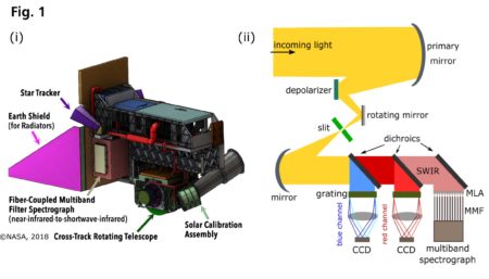
The central instrument of the PACE Satellite is a highly advanced optical spectrometer called the Ocean Color Instrument (OCI), that measures properties of light from ocean environments over portions of the electromagnetic spectrum from ultraviolet to short-wavelength Infrared (SWIR). A schematic showing the planned layout and principle of OCI can be seen in Fig. 1(i) and 1(ii) respectively.
Its advantage to previous NASA satellite sensors is its hyperspectral capability, i.e. improved spectral resolution of 5 nm when measuring the spectral range between 350-885 nm and large signal to noise ratios (SNRs). Moreover, to retrieve accurate ocean optical properties, OCI can remove unwanted reflectance contributions from the atmosphere (e.g. aerosol reflectance) and ocean surface. This atmospheric correction especially for near-shore regions or turbid waters is performed in the SWIR range where water absorption is few orders of magnitude greater than in the near infrared, ensuring nearly zero ocean reflectance.
The PACE Team at the Goddard Space Flight Center is currently developing the system to meet performance standards from scientists studying the atmosphere, ocean and even land surface.
The planned satellite will orbit around earths northern-southern hemispheres at an altitude of 675 km and consists of a cross-track rotating telescope that makes 360 rotations per minute and has a field of view of ± 56.5 °. For every instance in time, the telescope records an array of 1 x 16 spatial pixels also called “science pixels” by NASA where each pixel amounts to a 1 x 1 km geographical area measured at Nadir. Furthermore, to ensure high SNRs by building enough signal for integration, the telescope views the same geographical scene on earth for an extended time by imaging every “science pixel” 16 times, as it rotates.
This broadband light signal from oceans (acquired in the form of 16 spatial pixels) is reflected off a primary mirror (an off-axis parabola), depolarized and projected onto a rectangular slit. Thereafter, it is collimated and redirected using dichroic beam splitters to blue and red hyperspectral channels where dispersive gratings separate the individual wavelengths respectively and image them on time delay integration-charged coupled devices (TDI-CCDs). The SWIR bands are analyzed using a remotely located multi-band filter spectrograph that contains a temperature cooled 1 x 16 detector array. To couple light into the detector array, a 1 x 16 bundle of 600 µm core sized multi-mode fiber (MMF) with a numerical aperture of 0.22 is used. This is a superior approach than using 16 individual lens systems to couple incoming light from telescope to the detector array where precise mechanical alignment is cumbersome and prone to errors.
For efficient coupling of collimated light into the MMFs, NASA decided to use aspherical microlens arrays (MLA) with the requirement of low coupling losses. To minimize polarization dependent losses, both the MMFs and the MLAs required broadband anti-reflection coating from 0.9 to 2.3 µm. The goal is to be able to couple light over the entire spectrum with an efficiency of 95 percent.
The selection process
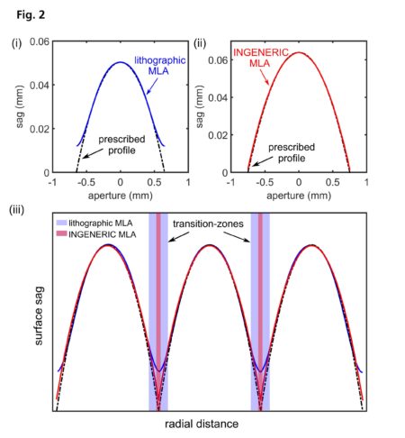
For the initial testing phase, NASA obtained commercially available lithographically produced quartz MLA with a pitch (lens center-to-center distance) of 1.3 mm. To determine the performance of the MLA, the surface profile of individual lenses was measured and compared with the desired lens surface profile where considerable deviations in surface sag profile at the lens edges of the lithographic lens were found (Fig. 2 (i)). During optical simulations with commercial software Zemax, the measured surface sag errors at edges showed an increase in the spherical aberration at the image plane, which has the consequence of decreased coupling efficiency into fibers.
Moreover, in the case of an array of aspherical microlenses, deviations of surface sag especially at the microlens edges can lead to the formation of dead transition zones (flat and shallow interfaces) between consecutive lenslets as shown in Fig.2 (iii). These dead zones were characterized using a laboratory bench-top imaging setup by NASA whose layout can be seen in Fig. 3(i).
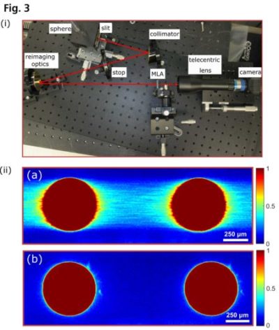
Using this setup, white light that passed through a rectangular slit located at the focal plane of the telescope was collimated, and redirected to illuminate the MLA. The MLA generated 16 round images of the telescope exit pupil, which were imaged using a telecentric lens on a SWIR camera. The resulting images showed leakage of ‘stray’ light from interfacial areas between the lenslets shown in part (a) of Fig. 3(ii) and can be attributed to presence of optical aberrations. In aspherical MLAs, the presence of spherical aberrations and transition zones has the consequence of reduced optical coupling efficiency of light into optical fibers.
In search of MLA where the coupling efficiency could be improved, NASA decided to test MLAs fabricated using a precision molding technique. For the second design phase, NASA tested aspherical MLAs from INGENERIC (Fig. 4) with a pitch of 1.5 mm. For this test phase, NASA increased both the lens radius of curvature and array pitch to compensate for changes in instrument layout.
At the beginning of the project, to ensure that the quality of the glass and coating meet the requirements, INGENERIC provided NASA with plane glass samples with a special anti-reflection coating optimized for the entire spectrum from 0.9 to 2.3 µm. Subsequent tests confirmed that the transmissivity requirements were met.

The next step was to test the accuracy of surface form of produced MLAs and their imaging properties. Using a commercial areal confocal 3D measurement setup (NanoFocus µsurf), the surface profile of the MLA was measured by INGENERIC and compared to the design requirements by NASA. As shown in Fig. 2(ii) a comparison of the two profiles showed an excellent agreement between the design requirements of NASA and the INGENERIC manufactured lens profile. This resulted in the INGENERIC produced MLAs to have transition zones that were almost an order of magnitude smaller than the MLAs produced by lithographic methods! Furthermore, pitch analysis of the INGENERIC MLA showed an exceptional accuracy with pitch errors <1 µm.
Furthermore, using the qualitative laboratory bench-top imaging test, NASA observed a considerable decrease in the ‘light leakage’ areas from the MLA interface (part (b) of Fig. 3(ii)), which again shows a qualitative improvement in the performance of the MLAs. While the previously used etched MLAs from other manufacturers did not meet NASA’s requirements, INGENERIC’s MLAs significantly exceeded the original expectations.
Both project partners attribute the superior performance of INGENERIC’s MLAs to the manufacturing process: Precision molding of aspherical microlenses that enables the design specifications for the shape of the lenses to be met with the highest precision. In this way, the lenses achieve optimum image quality. This is especially true for the edges of neighboring microlenses when coupling into glass fibers: If they are not manufactured precisely, light is scattered into the transition zones between the fibers and cannot be used for coupling. Here, too, the MLAs from INGENERIC perform impressively.
The current project status
The OCI will be built at the Goddard Space Flight Center in Greenbelt in the American state of Maryland. Laboratory tests are currently being carried out at component level (breadboard) to optimize the mechanical adjustment of the fiber bundles. The next steps will be the connection to the telescope and the examination of the entire optical path from the exit of the telescope to the entrance of the fibers. Integration into the Engineering Test Unit is planned for the summer of 2019. The satellite is expected to enter orbit in 2022.
Summary
During the development of the “Ocean Color Instrument” OCI for NASA’s PACE project, microlens arrays from INGENERIC, which the company manufactures using the precision molding process, proved to be far superior to etched arrays: They exceed the original requirements of the customer and will thus contribute to a significantly increased efficiency of coupling the light from the ocean surface into glass fibers of the satellite’s optical system.